The timber frames on the intersecting portion of the building that links the mill to the new build were added next. The roof on this portion of the building is lower (by 650mm ridge to ridge) and therefore the timber frame is lower too as the roof pitch remains at 30 degrees on both portions of the roof. This, in some ways, is an unwanted complication as it makes the valleys difficult to construct and the lead work for the valley fiddly where it has to wrap round the fascias of the higher roof, but from an aesthetic perspective it will likely look a lot better than having the roofs the same height so we feel that the extra effort will be worth it in the end.
The remaining timber frames built up.
The remainder of the frame was now fully covered in OSB sheets to stabilise the frame and provide a backing to the breather membrane. These were screwed on with copious amounts of 50mm screws and then the window apertures were cut out with a multi tool.
The frame now covered in OSB.
Tyvek ‘Housewrap’ breathable membrane was then stapled over the OSB on the exterior of the frame and 95mm x 47mm uprights installed every 400mm, these will eventually carry the exterior cladding on the top half of the building. These uprights were machined to half depth for the last 300mm so as to fit round the top course of blockwork (as they sit back from this on the timber frame) in order to eventually allow the cladding to come down to this level and hide the blockwork.
The housewrap and uprights being installed.
Work was now also focused on building up the two remaining internal block walls to support the ridge beams. There were two specific complexities to these as they both needed to turn through 45 degrees as per the walls below (these were done this way for aesthetic purposes to ‘open’ up the atrium part of the building a bit more) and they needed to incorporate steel uprights that would ultimately hold a cranked beam to support the intersecting roof ridge beam/provide support for the roof valleys. This made building them up quite precarious as they had little support until the steelwork was all in place (tied into the walls) and there was some proper weight on them to help stabilise them from any lateral movement. As such, they were bult up carefully with multiple stabilising timbers fixed to them until they had the requisite height and weight upon them.
The internal block walls being built up with the steel uprights integrated into them.
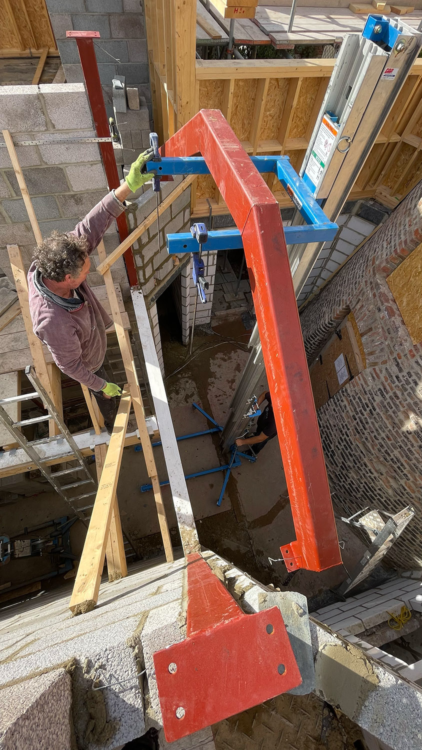
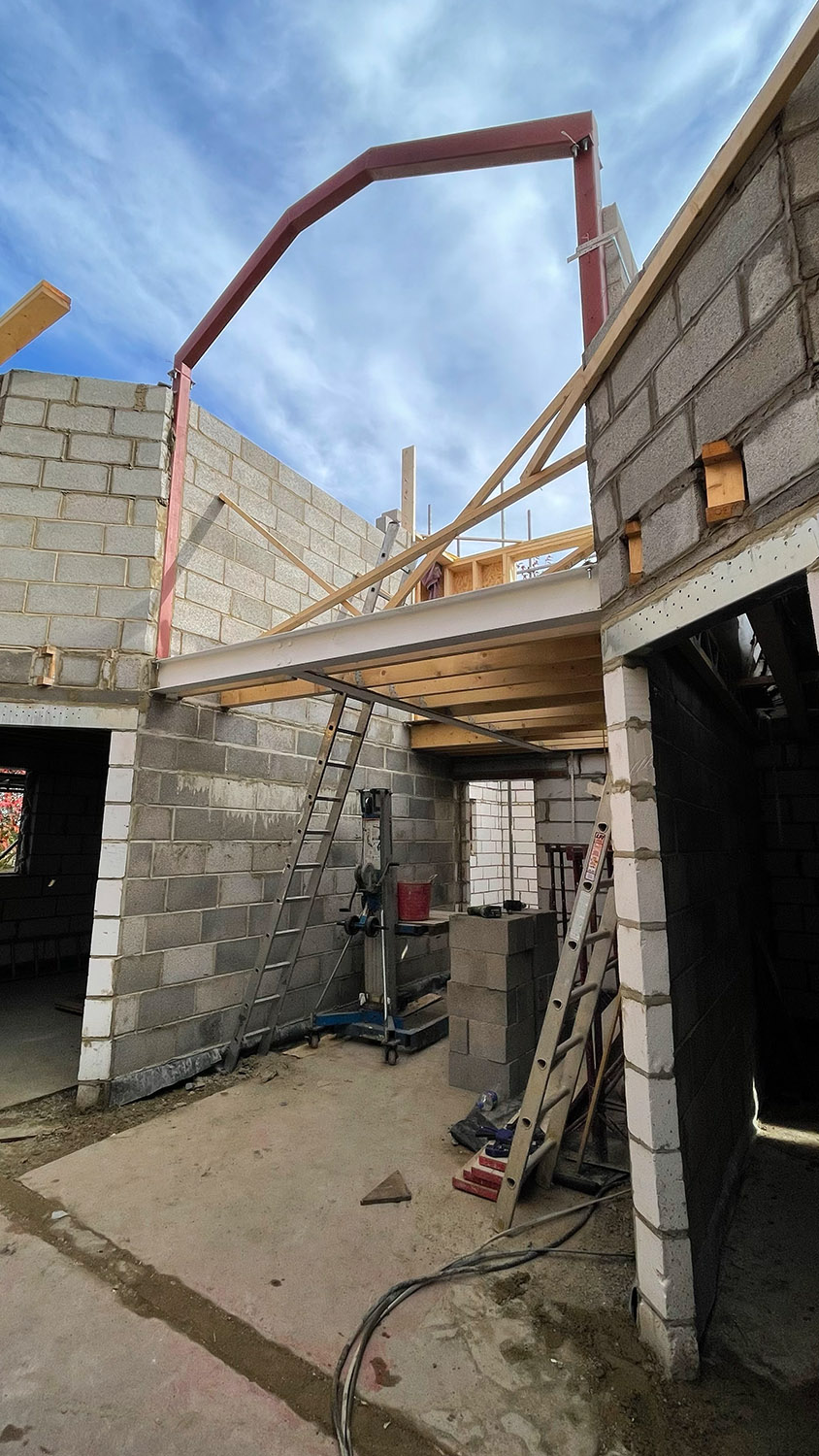
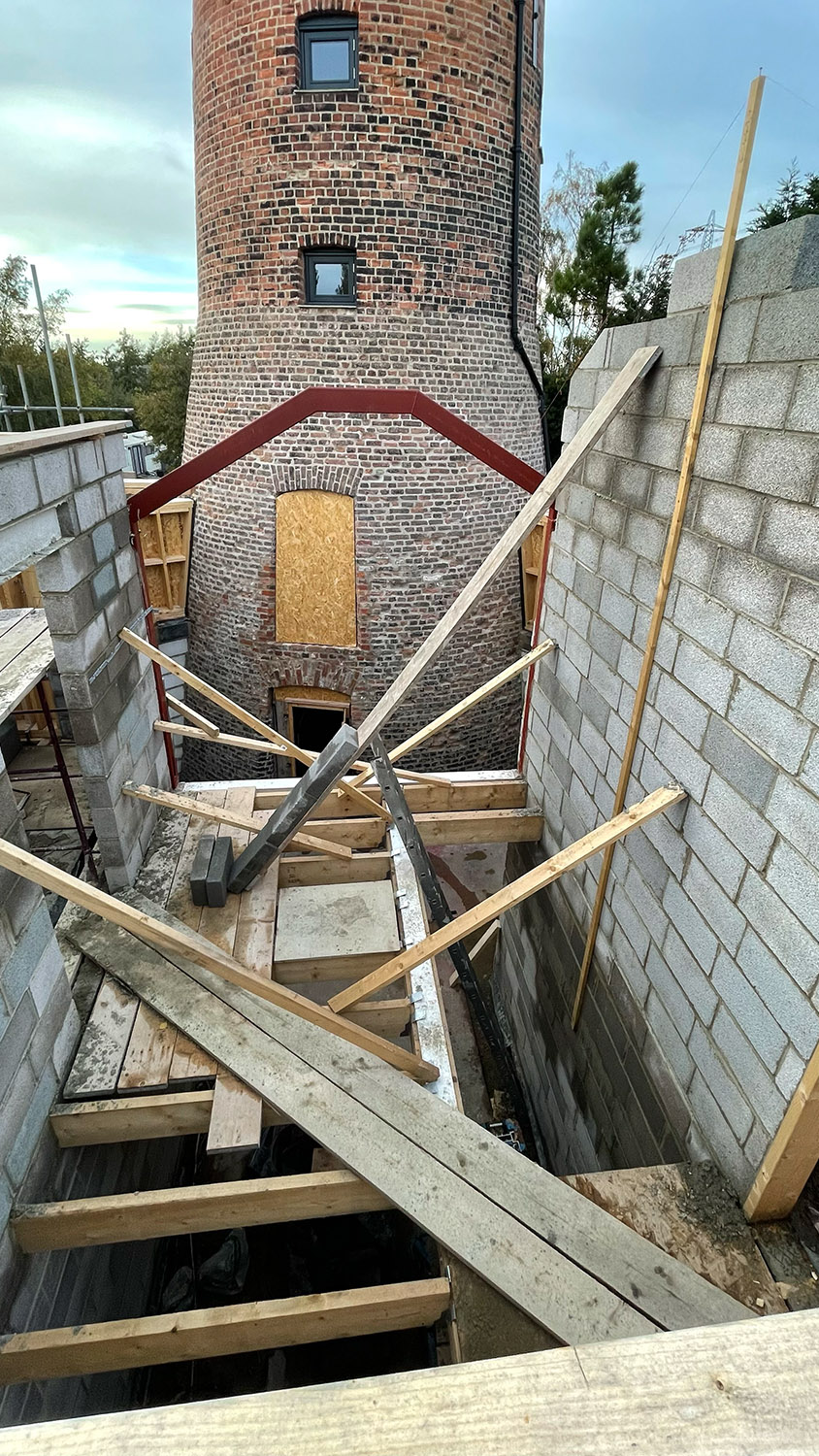
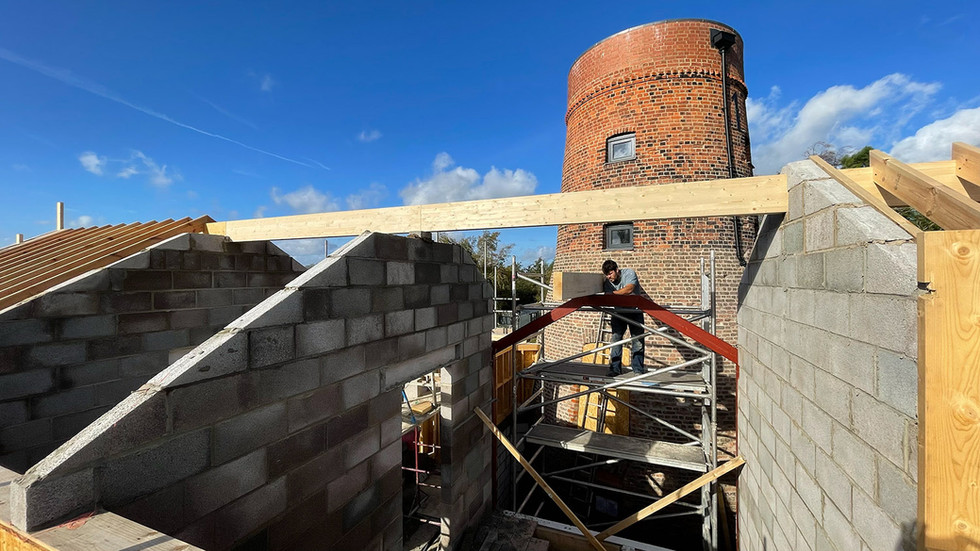
With the uprights in place and bolted to the steel crossmember delimiting the landing floor from the ‘atrium’, and the walls nearly up to ceiling height it was time to install the cranked beam. Designing this had been a bit of a nightmare as we had no structural drawing from the architect so had to work it out ourselves using laser levels for measurement and lots of trigonometry. The difficulty was working out where the valley timbers would intersect the cranked beam and getting that height exactly right, this was made more complex by the fact that the internal walls are not symmetrical with the ridge of the intersecting roof so one crank is longer than the other. Eventually, however we had a 3 piece cranked beam with two uprights (of different lengths) and an offset crank that bolts to plates welded onto the uprights. Getting it up there was the next conundrum as it’s a high lift and too heavy/cumbersome to do manually so we hired a 6m Genie lift and winched it up whereupon with one person either side of the beam we could bolt it on to the uprights. This was one of those ‘major milestone’ moments as the whole 'cranked beam/no architect drawings for it' thing had been nagging at us right from the start so to finally see it in place was significant and a welcome sight.
The cranked beam being installed.
Work then continued on the internal walls to finish them off to roof height and get the ridge beams installed including the intersecting roof ridge beam that was of course sat lower than the main roof. This was inserted into the wall of the mill, levelled and then bolted to the cranked beam via a ‘U shaped’ steel support that was welded to the beam in situ. After this more rafters were installed and at long last you could see the skeleton of a house emerging.















תגובות