BUILDING THE NEW MILL ROOF FRAME
- Chris Berry
- Oct 18, 2021
- 4 min read
Updated: Jan 15, 2023
With the old roof now gone it was time to build the new one. In terms of the design we wanted to sit the roof down inside the mill walls and therefore a standard ‘cold roof’ where the insulation is between the timbers and the void above them must be ventilated was not an option as there was no way to get ventilation into the roof space due to the roof being surrounded by brickwork. Instead, we went with the option of a ‘warm roof’ where the vapour control layer sits above the roof timbers, but below the insulation. In terms of the final finish we wanted to use metal (either zinc or lead) with a central drain ‘trough’ like church roofs often have on their towers.
A church roof showing the type of drainage and finish we were looking for albeit not with the access hatch.

I was very keen to insulate the roof as well as possible and it seems the standard design for such roofs with a central trough is not to insulate underneath the trough as otherwise the roof structure ends up too complex and costly, so effectively the trough usually just sits between the insulation. However, given the fact that the top room in the mill was to be a bedroom and the walls themselves aren’t exactly a prime example of thermal retention it seemed sensible to insulate the roof as much as possible so I devised a two layer timber roof frame that would effectively be one solid frame on the bottom and two half frames on the top with a gap down the middle the take the trough. Importantly though this gap would be wide and deep enough to allow insulation to go under and next to the trough thereby ensuring the roof was fully insulated. In terms of how to support the frame there is a convenient ledge inside the mill tower walls at just the right height where the walls step from 450mm thick down to 225mm thick giving a 225mm ledge all the way round the inside of the wall. The plan was to install a wall plate on this ledge and then sit the roof frame on it to provide a solid level support with the frame being anchored down to the internal walls with restraint straps.
I then researched the exact materials needed for the frame, decking, vapour control layer and insulation and came up with the following specification:
Timber framing - 220 x 47 C24 softwood.
Decking (2 layers) – 18mm OSB 3 tongue and grove.
Insulation – Celotex XR4140
Vapour control layer – Alutrix 600 VCL
We also decided that we would use lead on the roof instead of zinc as it would give a more authentic look, but we realised that fitting this properly and neatly was likely beyond our capabilities and therefore we contacted a local lead working to come and install this, but with us still doing everything else on the roof first.
The design for the roof is shown in these schematics.
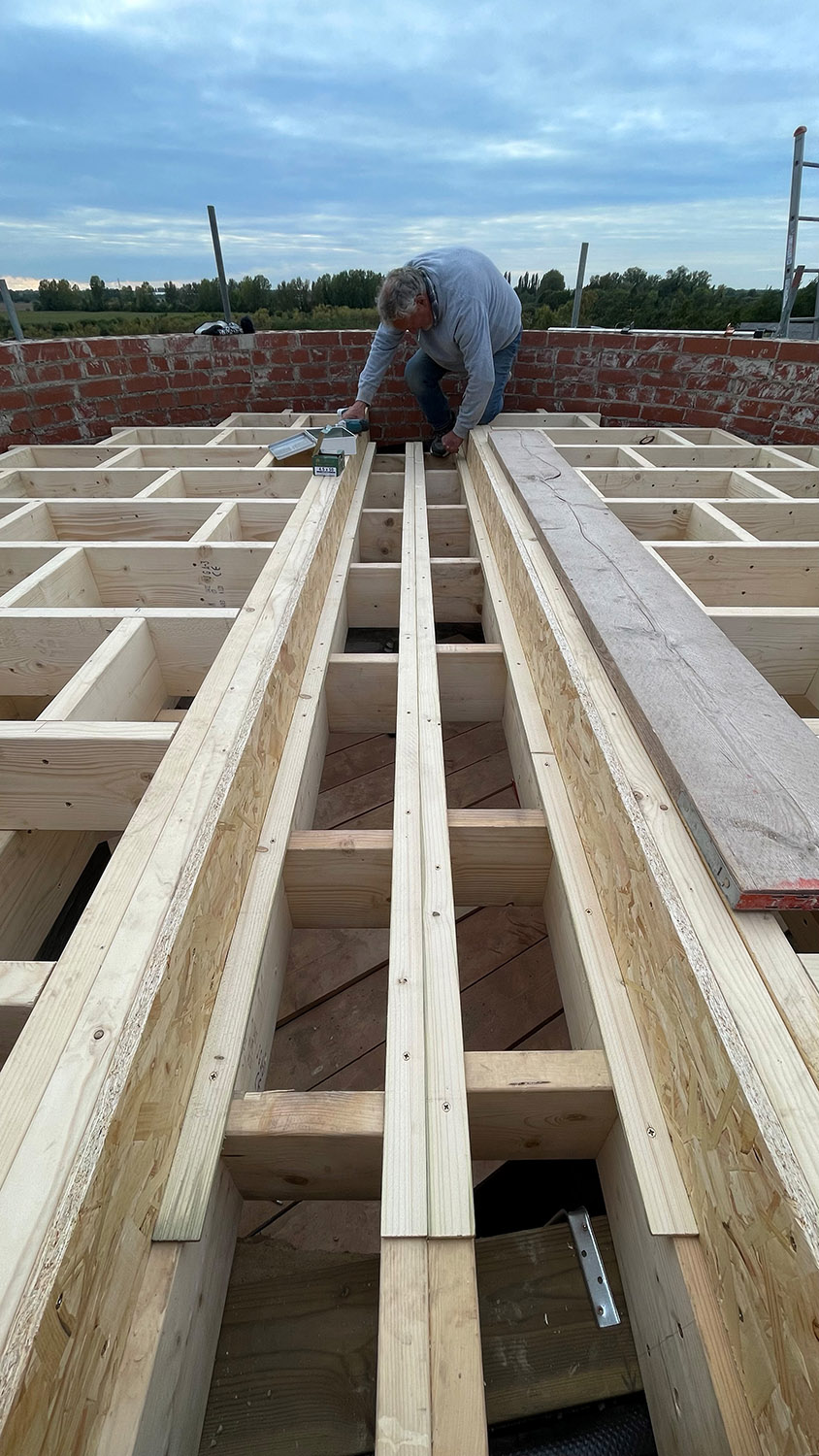
Once again, we were faced with getting all the materials and equipment to make and fit the roof up on to the top of the scaffold. Anything small went up on the winches but the 220 x 47 timbers were 'hand-balled' up the tower by five of us in a line (one on each lift of the scaffold) and this was then cut to size up on the top lift (via an immensely heavy Makita chop saw that we also had to winch up. The wall plate was cut (made up of 12 interlocking lengths of 97 x 47 going round the inside ledge like a large dodecagon), bedded on sand/cement and levelled. Once this had set the first layer frame was built in situ as per the schematic design shown above with the timbers being glued and screwed together. The centre (doubled) timbers were positioned first and then the frame was 'worked out' from there with cross members spaced every 400mm and noggins at 600mm centres between them.
The lower frame being built.
Next up the second layer of framing was built up in the same way as the first, but this time with a precise gap left down the middle to accommodate the drainage trough and two thicknesses of insulation. Fillet timbers were then installed to ensure the water would run off the main roof into the trough and then down the trough and through the wall into the hopper. The first layer of 18mm OSB was then installed on top of this frame which was yet another logistical challenge due to the height involved. The solution was to cut the OSB on the ground (circular cuts are so lovely) and leave a ‘tab’ on each of these that we could then drill a hole through for a rope that could be used to haul them up on the winch. The tab was then cut off at the top before fitting.
The second layer of frame being built and the OSB deck installed (including some emergency protection added due to an impending overnight rainstorm).
The deck was then filled round the edges with expanding foam in readiness for the installation of the vapour control layer.


Comments