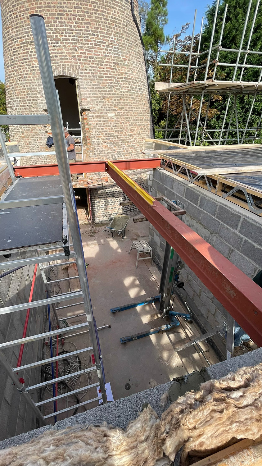
When the posi-joists were installed for the first floor the landing was left out as this is a much shorter span side to side (3.6m) which will work just fine with standard timber joists and needs the opening for the stairs as well as a support beam across the end of the double floored area where the bridge will eventually allow access to the mill within the double height ‘atrium’ (for want of a better expression). We were originally going to have a spiral staircase, but this idea was abandoned on cost and space grounds and instead we settled on a ‘floating’ staircase mounted up the side of the east internal wall. This meant we needed a sizeable opening and therefore it was decided to install two 203 x 133 UB steel beams, one across the end of the upper floored area and the other connected to this at 90 degrees to form the opening for the staircase and provide a mounting for the floor joists on the landing. The steel was sourced from a local supplier and the beam across the end of the first floor was fitted first with the second beam being bolted to it and positioned accordingly to form the staircase aperture.
The landing steel beams being installed.
With the sole plate in place all round the building the timber frame could now start being erected. Many builds involving timber frames have the frames made up off site and then just lifted and fitted on site, but we were building on a rather rudimentary original footprint where the building wasn’t quite square (the good old 1970s building standards). As such, we decided to build the frames up in situ as that way we’d be assured of accuracy and remove any potential pre-fabrication headaches. The frames have two 195mm x 47mm timbers top and bottom and 195mm x 47mm timbers at 400mm centres with horizontal noggins every 1.2m (vertically). Everything is screwed together as I prefer screws to nails simply because you can take them out if an error occurs (and with me they do... more often than I’d like to admit). We elected to start with an easy wall with no windows at the west end of the building as a sort of trial as to our methodology and happily, all went well. From here we built up the west gable and the wall on the other side of the building connected to this leaving apertures for the windows where necessary.
The start of the timber frame construction.
Work continued with the frame installing the east gable and completing the frame on the main building. The overhangs left on the walls near the mill in the following pictures are deliberate as with the intersecting roof being lower there need to be some small triangular sections of wall there and these would be bracketed, cut back accurately and then built up at a later date.
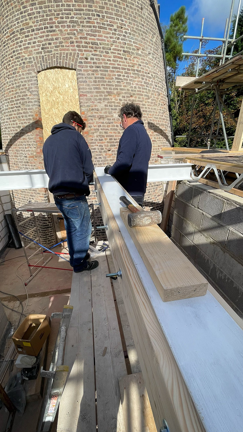
The landing floor joist were installed as the next task and this meant bolting timbers to the steel work on the landing and then using joist hangers to hang 245 x 47 timbers at 400mm centres off these with the other end sat on the intermediate concrete block walls. These would then be infilled when the walls were built up for the second storey.
The landing floor joists being installed.
In the meantime the front garden wall was taking shape.

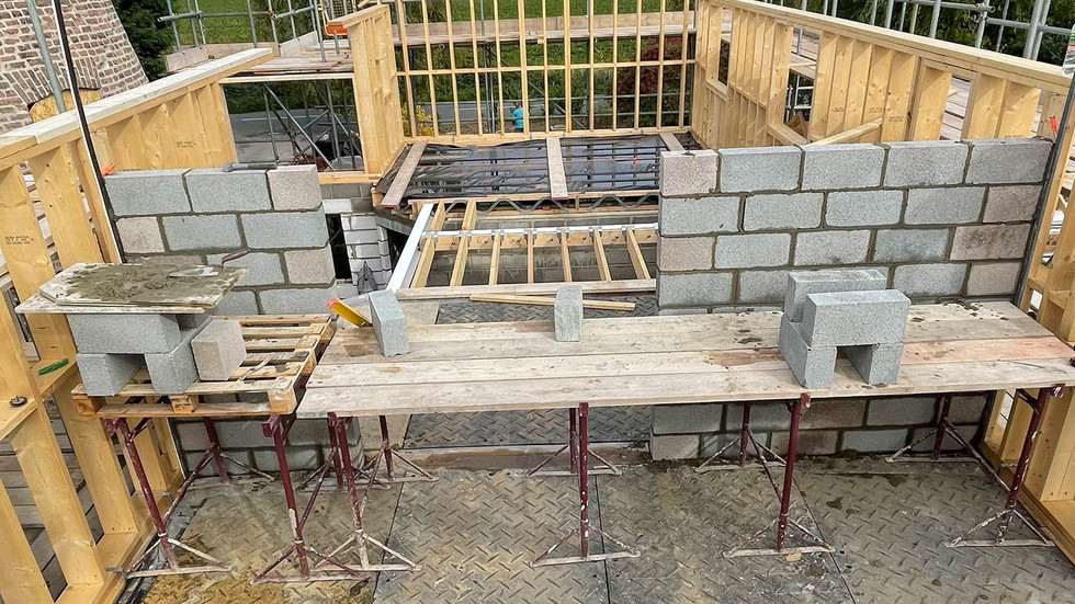
With the landing floor joists in position the three second storey internal block walls that were to bear the ridge beams for the roof could start to be built up (two on the hall walls and one on the beam we installed across the living room). All of these had openings for doorways so needed to be built around these and have further steel beams put in above the openings. The first one to go up was the one over the living room sitting on the beam and we made a temporary ‘A frame’ to sit on the timber frame and give an exact position of the roof line so the blocks could be shaped accordingly. Once this was up to height we installed the first of the four ridge beams for the main building with one end on the block wall and the other on the gable end timber in a specially constructed ridge beam support aperture.
First of the internal block walls going up, temporary ‘A frame’ in position and ridge beam installed... and the building inspection cat on site.
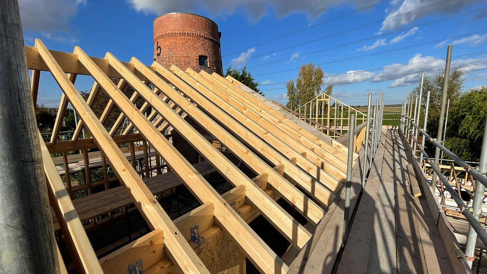
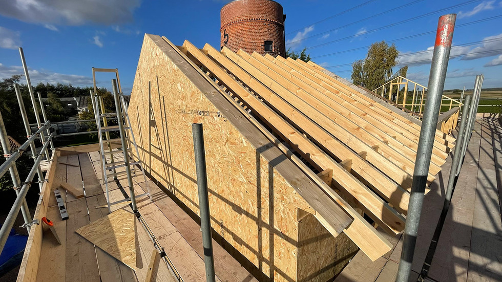
While the other two block walls were being built we put the rafters on the section that now had the ridge beam, and clad that end of the timber frame in 12mm OSB sheets in order to solidify it and provide a backing for the breather membrane. The rafters are 175mm x 47mm and set at 400mm centres for additional solidity. They are step cut to fit the ridge beam and anchored on the wall plate by 200mm screws and noggin blocks that are themselves bracketed to the frame.
The first rafters and OSB cladding installed on the east end of the building.










Comentarios